
The TT34 is an envelope temperature sensor for hot air balloons, and has been around for at least 15 years, so many people own one. It was intended to be used together with the (now discontinued) Flytec 3040 Vario:
I got curious if one could receive the sensor values from the TT34 with other hardware, maybe a small microcontroller with a suitable receiver for the 433Mhz band (or 418Mhz for USA). So I had a look at the transmission and protocol messages sent by the TT34. For a start, I disassembled the TT34 and the Flytec 3040 and had a look at the electronics.
A particular TT34 and an 3040 are “paired” with a serial number, so any 3040 will receive data only from it’s paired counterpart. The serial is printed on the case, in my case it is a 4-digit number (5850 or 0x16DA hex).
Electronics
The TT34 has an AM-RT4 transmitter module and the Flytec 3040 has a Philips UAA3201T receiver. Both are for AM (amplitude modulation) – the RT-4’s “data input” pin is really a “transmitter on/off” pin. So the transmission method is really a glorified morse code – the receiver manual describes it as “AM Return-to-Zero (RZ) Amplitude Shift Keying (ASK) modulation”. So – step1: record the signal:
Transmission signal
I recorded the transmission with an old scanner radio to a wav file – it looks like so in Audacity:

This is how it sounds:
There’s clearly a bit pattern maybe 5 or 6 bytes long, but decoding that looks challenging. So I opened the TT34 and connected a logic analyzer to the data pin of the transmitter chip – much clearer picture:
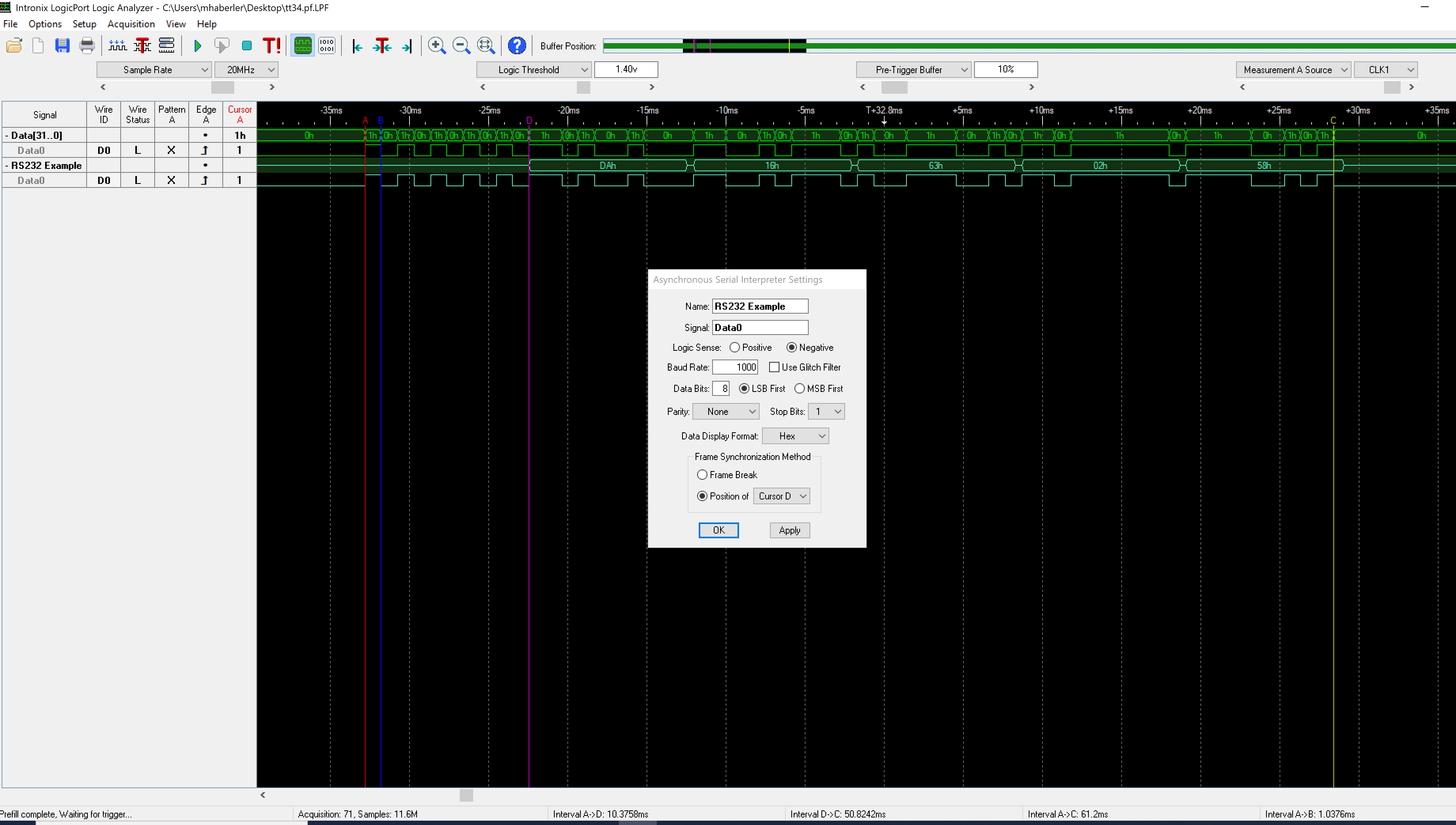
Timing and packet structure
With a bit of staring at the display and playing with decoding parameters it became clear:
- The duration of the bit pattern is 1mS.
- The overall transmission length is about 60 bits or so.
- The signal can be decoded as an asynchronous bit stream, 8bits, 1 stop bit, no parity (so total 10 bits/character) which makes the message 6 bytes long – this fits with the 60 or so bits mentioned above.
- The RS232 decoder of my LogicPort Analyzer can decode the message fine when setting the bitrate to 1000bps (not 1200bps!), so it looks like an async transmission with a non-standard bitrate.
- There is a fixed pattern at the beginning (0x55) and varying bytes thereafter.
- The first two bytes correspond to my serial number (0x16DA)
- The two following bytes are the temperature encoded as two decimal numbers – the value in the picture (63h 02h) is displayed as 26.3° on the Flytec 3040.
- there is a trailing byte of varying content. I assumed it might be a checksum to guard against transmission errors, but it is not – none of the 8bit checksum algorithm in the Python crccheck package revealed any clues.
- After studying the manual I noticed that the TT34 can report a broken sensor, and that fact is displayed by a special symbol in the temperature display field. I disconnected and reconnected the sensor and observed how the trace changes: it turns out that a broken sensor toggles bit 0x04 in the last byte of the transmission – if it is set, this indicates a broken sensor. The other fields have a known purpose, so the last byte is some flag field.
- I was unable to guess the meaning of the remaining bits in the last byte – they do change between transmissions.
I did try to decode the TT34’s transmission with a SX1278 chip operating in the “OOK” (on-off-keying) mode, but was unable to detect or decode any transmission so far – so, as the say: “more research is needed..”.
Decoding the radio transmission
I recently found an interesting tool to reverse-engineer digital radio transmissions: Universal Radio Hacker (urh) and decided to give the RF side a spin with my HackRF software-defined radio while exploring urh.
Investigate the radio spectrum
The Spectrum analyzer view makes it easy to detect the radio transmissions:
Record the transmission
we record at 2M samples/second and capture two transmissions:
When done, close the record signal window and we’re off to interpretation:
Interpretation view
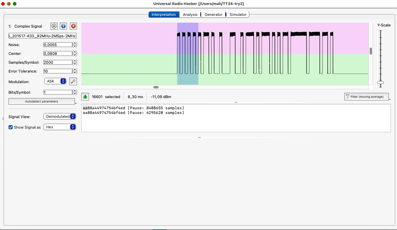
urh has a phenomenal autodetection code – it recognizes bit timing really well and tries to decode the bit stream.
Analysis view
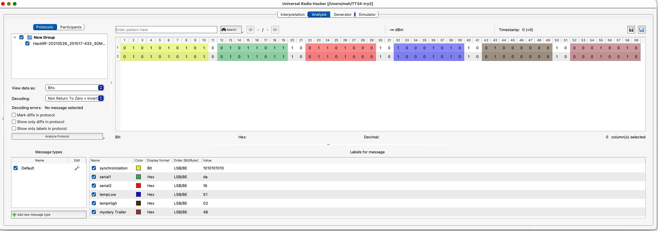
The analysis enables us to annotate the bits and their meanings. Luckily the results are identical to the logic analyzer view!
The urh project and sample file can be found on github.
Summary
With the findings above it should be possible to receive and decode the TT34’s transmissions, match a given serial number, and detect a broken sensor.
If anyone in the know has more details on the TT34 protocol: drop me a note and I will update this post.
Update: a TT34 decoder does exist
It turns out the formidable Oliver Wipfli has written such a decoder. The code can be found here.